 Skip to content


Vehicle Speed Sensors (VSS) are crucial components in modern vehicles, playing a vital role in monitoring and controlling various systems.
These sensors measure the speed of a vehicle's wheels or transmission, providing essential data to the engine control unit (ECU) and other onboard systems.
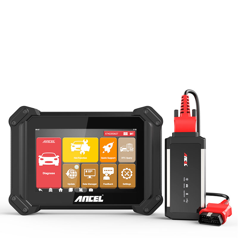
ANCEL V6 Pro car scanner offers an advanced diagnostic tool capable of detecting issues across the entire vehicle, including the ECU.
This professional-grade device not only reads and clears trouble codes but also supports ECU coding, making it an indispensable tool for both professional mechanics and car owners.
How Do Vehicle Speed Sensors Work?
Functionality of VSS
Vehicle Speed Sensors (VSS) are intricate devices designed to precisely measure and report the rotational speed of a vehicle's wheels or transmission.
These sensors play a crucial role in the overall functionality and performance of a vehicle.
Let's delve into the detailed process and mechanisms by which VSS operate:
Signal Generation
The core function of VSS is to generate a signal that correlates with the rotational speed of the vehicle's wheels or transmission.
This is typically achieved through different types of sensors such as magnetic inductive sensors, Hall effect sensors, and optical sensors.
Magnetic Inductive Sensors:
These sensors consist of a toothed wheel (reluctor) and a magnetic coil.
As the reluctor wheel rotates, the teeth pass by the magnetic coil, disrupting the magnetic field and generating an alternating current (AC) signal.
The frequency of this AC signal is directly proportional to the rotational speed of the wheel or transmission.
Hall Effect Sensors
These sensors use a Hall element that reacts to changes in a magnetic field.
When a ferromagnetic object, such as a gear tooth, passes by the sensor, it alters the magnetic field, creating a voltage signal.
The frequency of this voltage signal corresponds to the speed of the rotating object.
Optical Sensors
These sensors employ a light-emitting diode (LED) and a photodetector.
A rotating disk with slots interrupts the light beam from the LED to the photodetector, generating a pulse signal.
The rate of these pulses is indicative of the rotational speed.
$439.99
Data Transmission
Once the VSS generates the signal, it needs to be transmitted to the vehicle's Engine Control Unit (ECU) or other relevant systems.
This transmission is typically done through electrical wiring or, in advanced systems, wirelessly.
The signal can be analog or digital, depending on the sensor type and vehicle system configuration.
-
Analog Signals: Generated by magnetic inductive sensors, these are continuous waveforms where the frequency and amplitude of the signal correspond to the speed of rotation.
-
Digital Signals: Typically generated by Hall effect and optical sensors, these are pulse signals where the number of pulses over a given period indicates the speed.
Related Reading: Guide To Using Obd2 Scanners For Ecu Coding
Data Processing
The ECU or relevant control unit receives the signals from the VSS and processes the data to perform various functions.
The ECU uses algorithms to interpret the frequency and pattern of the signals, converting them into meaningful data such as vehicle speed, wheel rotation rate, and transmission output speed.
-
Fuel Injection and Ignition Timing: The ECU adjusts the fuel injection rate and ignition timing based on the vehicle speed data to optimize engine performance and fuel efficiency.
-
Transmission Control: The Transmission Control Unit (TCU) uses VSS data to determine the optimal shift points for smooth gear transitions in automatic transmissions.
-
Safety Systems: Systems like Anti-lock Braking System (ABS) and Traction Control System (TCS) rely on VSS data to monitor wheel speed and prevent wheel lockup or slip, enhancing vehicle stability and safety.
-
Driver Information Systems: VSS data is also used to provide real-time information to the driver through the speedometer and other dashboard indicators.
Error Detection and Diagnosis
Modern VSS are equipped with self-diagnostic features that allow them to detect and report malfunctions.
The ECU constantly monitors the signals from the VSS for any anomalies that might indicate sensor failure or signal interference.
If an issue is detected, the ECU logs an error code and may illuminate the check engine light to alert the driver.
-
Consistency Checks: The ECU compares VSS data with inputs from other sensors (e.g., wheel speed sensors) to ensure consistency. Discrepancies can indicate a faulty VSS or related issue.
-
Signal Integrity: The quality and integrity of the VSS signal are continuously monitored. Issues such as weak signals, noise, or interruptions can trigger diagnostic trouble codes (DTCs).
By providing detailed, real-time data on vehicle speed, VSS ensure that various systems operate in harmony, contributing to the vehicle's overall performance, safety, and efficiency.

Image From The Clemson University Vehicular Electronics Laboratory
Applications of Vehicle Speed Sensors
Engine Management
Vehicle Speed Sensors provide critical data to the ECU for optimizing engine performance.
The ECU uses VSS data to adjust fuel injection, ignition timing, and air-fuel mixture, ensuring efficient combustion and reducing emissions.
This real-time adjustment is crucial for maintaining the engine’s efficiency, preventing knocking, and enhancing fuel economy.
By constantly monitoring vehicle speed, the ECU can make precise adjustments that keep the engine running smoothly under various driving conditions.
Transmission Control
In automatic transmissions, VSS data is essential for smooth gear shifting.
The Transmission Control Unit (TCU) relies on speed sensor inputs to determine the optimal shift points, enhancing driving comfort and fuel efficiency.
When the vehicle accelerates or decelerates, the TCU adjusts the gear ratios to match the speed, ensuring seamless transitions and preventing unnecessary wear on the transmission components.
This precise control helps in extending the life of the transmission and improving overall vehicle performance.
Anti-lock Braking System (ABS)
The ABS uses VSS data to monitor wheel speed and prevent wheel lockup during braking.
By modulating brake pressure, the ABS maintains traction and steering control, improving safety in emergency braking situations.
When the ABS detects a wheel losing traction and beginning to lock up, it rapidly pulses the brake pressure to that wheel, preventing skidding and allowing the driver to maintain control of the vehicle.
This technology is particularly beneficial in wet or icy conditions, significantly reducing the risk of accidents.
Speedometer and Odometer
The speedometer and odometer rely on VSS data to display accurate vehicle speed and distance traveled.
This information is crucial for drivers to maintain safe speeds and track vehicle usage.
The speedometer provides real-time feedback on how fast the vehicle is moving, while the odometer records the total distance traveled, which is essential for maintenance schedules and resale value assessment.
Accurate speed and distance measurements also play a role in navigation systems and fuel efficiency calculations.
Traction Control and Stability Control
Traction control and stability control systems use VSS data to detect wheel slip and adjust engine power or apply brakes to maintain vehicle stability.
These systems enhance safety by preventing loss of control in slippery conditions.
Traction control reduces power to the wheels when slip is detected, ensuring the vehicle maintains grip.
Stability control uses VSS data to apply brakes to individual wheels and reduce engine power, helping to correct oversteer or understeer and keep the vehicle on its intended path.
Advanced Driver Assistance Systems (ADAS)
ADAS Integration
ADAS technologies such as Adaptive Cruise Control (ACC), Lane Keeping Assist (LKA), and Automatic Emergency Braking (AEB) heavily rely on accurate VSS data. These systems utilize speed data to make real-time decisions that enhance driving safety and comfort.
Adaptive Cruise Control (ACC)
ACC systems use VSS data to maintain a set speed and distance from the vehicle ahead.
By constantly adjusting the throttle and brakes, ACC helps reduce driver fatigue and improve fuel efficiency during long drives.
The system monitors the speed of the vehicle and the distance to the car in front, automatically slowing down or speeding up to maintain a safe following distance.
Lane Keeping Assist (LKA)
LKA systems rely on VSS data combined with camera inputs to keep the vehicle within lane markings.
If the system detects unintentional lane departure, it can apply corrective steering or braking to maintain lane discipline.
VSS ensures that the lane-keeping system adjusts accurately based on the vehicle’s speed, providing timely corrections to keep the vehicle safely in its lane.
Automatic Emergency Braking (AEB)
AEB systems use VSS data along with radar and camera inputs to detect potential collisions.
If an imminent collision is detected, the system can automatically apply the brakes to prevent or mitigate the impact, enhancing passenger safety.
VSS data helps the system calculate the speed and distance to the obstacle, ensuring the brakes are applied with the right force and timing to avoid or lessen the collision.
Vehicle Dynamics Control Systems
Electronic Stability Control (ESC)
ESC systems use VSS data to monitor vehicle dynamics and prevent skidding or loss of control.
By selectively applying brakes to individual wheels and reducing engine power, ESC helps maintain vehicle stability during sharp turns or slippery conditions.
VSS provides the speed information necessary for the ESC system to detect and correct any instability, ensuring the vehicle stays on course.
Hill Start Assist (HSA)
HSA systems utilize VSS data to prevent rollback when starting on a hill.
By holding the brakes momentarily after the driver releases the brake pedal, HSA allows smooth and confident hill starts.
The VSS ensures that the system knows exactly when the vehicle starts to move, releasing the brakes at the right moment to prevent rollback and provide a seamless start.
Common Issues with Vehicle Speed Sensors
Over time, Vehicle Speed Sensors can wear out or become damaged due to exposure to harsh conditions. Common symptoms of a failing VSS include erratic speedometer readings, transmission shifting issues, and activation of the check engine light.
Physical Damage
Physical damage to the Vehicle Speed Sensor (VSS) can occur due to impact from road debris, rough terrain, or accidents. This damage can cause the sensor to malfunction or fail entirely. Common symptoms of physical damage include:
-
Broken or Bent Components: The sensor or its mounting bracket may become bent or broken, leading to misalignment and incorrect readings.
- Cracked Housing: The protective housing of the sensor can crack, exposing the internal components to the elements and causing failure.
Electrical Problems
Faulty wiring or poor electrical connections can lead to VSS malfunction. Issues such as corroded connectors, frayed wires, or loose connections can disrupt the signal transmission between the sensor and the ECU.
Common Electrical Issues
-
Corroded Connectors: Exposure to moisture and road salt can corrode the electrical connectors, leading to intermittent or no signal.
-
Frayed or Damaged Wires: Wires can become frayed or damaged due to rubbing against other vehicle components or being pinched during vehicle operation.
- Loose Connections: Vibrations and vehicle movement can cause electrical connectors to become loose, resulting in poor signal transmission.
Contamination
Dirt, debris, and metal particles can accumulate on the sensor or its mounting area, leading to inaccurate readings.
Regular maintenance and cleaning of the sensor and its surroundings can help prevent contamination-related issues.
Sources of Contamination
-
Road Debris: Dust, mud, and small stones from the road can build up on the sensor.
-
Metal Shavings: Metal particles from brake wear or other vehicle components can stick to the sensor, especially magnetic ones.
- Oil and Grease: Leaks from the engine or transmission can coat the sensor, interfering with its ability to detect speed accurately.
Interference from Other Electronic Devices
Interference from other electronic devices within the vehicle can sometimes cause VSS to malfunction.
Ensuring proper shielding and grounding of electrical components can mitigate these issues.
Devices that emit high-frequency signals can disrupt the VSS signal, leading to incorrect readings.
Common Sources of Interference
-
Mobile Phones and Radios: High-frequency emissions from mobile phones and radios can interfere with VSS signals.
-
Aftermarket Electronic Devices: Installation of aftermarket electronic devices like navigation systems or dash cams can introduce electrical noise that affects VSS performance.
- Faulty Alternator or Ignition System: Electrical issues from the alternator or ignition system can create noise and interfere with sensor signals.
Signal Interference
Signal interference can occur when the sensor's signal is disrupted by external factors.
This interference can lead to inaccurate speed readings or complete sensor failure.
Causes of Signal Interference
-
High Voltage Lines: Proximity to high voltage lines within the vehicle can disrupt the sensor's signal.
-
Radio Frequency Interference (RFI): External RFI from nearby sources such as radio towers can interfere with the sensor's signal.
- Electromagnetic Interference (EMI): EMI from other electronic components within the vehicle can cause signal disruption.
Error Codes and Diagnostics
Modern vehicles are equipped with onboard diagnostic systems that can detect issues with the VSS. When the ECU detects a problem with the sensor, it stores a diagnostic trouble code (DTC) and may illuminate the check engine light.
Common Diagnostic Trouble Codes (DTCs)
-
P0500: Vehicle Speed Sensor Malfunction - This code indicates a general fault with the VSS.
-
P0501: Vehicle Speed Sensor Range/Performance - This code signifies that the sensor is not operating within the expected range or performance parameters.
-
P0502: Vehicle Speed Sensor Low Input - This code indicates that the signal from the sensor is lower than expected.
- P0503: Vehicle Speed Sensor Intermittent/Erratic/High - This code signifies that the sensor signal is erratic or higher than expected.
Conclusion
Vehicle Speed Sensors (VSS) are indispensable components in modern vehicles, contributing to engine management, transmission control, braking systems, and various safety features. As technology advances, VSS will continue to play a pivotal role in the development of more sophisticated and reliable automotive systems.
FAQs
How can I prevent my Vehicle Speed Sensors from failing?
Regular maintenance, keeping the sensors clean, and addressing electrical issues promptly can help prevent sensor failure.
Is it possible to test a Vehicle Speed Sensor at home?
Yes, with the right tools, such as a multimeter, you can test the sensor's electrical output to diagnose potential issues.
How does a Vehicle Speed Sensor improve vehicle safety?
VSS data is crucial for the proper functioning of safety systems such as ABS, traction control, and stability control, which prevent skidding and maintain vehicle stability.
Recommended Similar Articles:
- Mass Airflow Sensor: What, Where, and Why It Is Important
- Warning Signs of a Cracked Cylinder Head: Symptoms, Causes, and Solutions
- [How To] After Changing Spark Plugs, Why Is My Car Idle So High?
- 7 Bad Crankshaft Position Sensor Symptoms [+ How to Fix]
- What Causes the Code P0446 on Chevy Silverado? We’ve got you covered with all solutions


